How To Connect and Use a Push Button With Arduino
Author: Ihechikara Abba

You can use push-buttons for different reasons in Arduino, such as turning on/off LEDs, starting and stopping a motor, interrupting and triggering certain actions in a program, and so on.
In this article, you’ll learn how to connect a push-button to an Arduino board. You’ll also see how to interact with a push-button using code.
You’ll make basic connections using jumper wires and a resistor (including diagrams), and how to get the current state of a push-button using Arduino code.
This article is beginner friendly so you can still follow along even if you don’t have a solid understanding of how Arduino works. This should help you expand your knowledge of it.
Let’s get started!
Hardware Components
- Arduino UNO.
- Breadboard.
- Jumper wires.
- 1K Ohm resistor.
- Push-button.
How To Connect a Push Button to Arduino Board
In this section, you’ll learn how to connect a push-button to an Arduino board.
There are different ways of connecting a push-button to the Arduino board:
- You can connect to a power source and ground (GND), then specify if the push-button will be a pull-up or pull-down input.
- You can use a resistor to connect the push-button as either pull-up or pull-down.
None of the connections above are wrong - it’s up to you to decide. In this article, we’ll use the latter.
A pull-up resistor sets the initial state of the push-button as HIGH while a pull-down resistor will set the current state as LOW.
Here’s the circuit diagram for the connection:
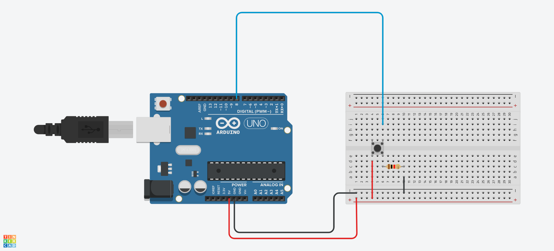
From the circuit above, you can connect a push-button to the Arduino board by connecting:
- One leg of the push-button to 5-volt power supply on the UNO board.
- The other leg to GND through a pull-down resistor.
- A digital pin (pin 8 in our circuit) to the other end of the GND leg.
Connecting the resistor to GND sets the push-button’s state to LOW (0). The resistor is known as a pull-down resistor.
On the other hand, it would be a pull-up resistor if it was connected to the power supply. This would set the initial state to HIGH (1).
To be sure our connection is working, let’s print the current state of the push-button to the serial monitor using code:
int push_btn_pin = 8;
int pushBTN_state;

void setup(){
  Serial.begin(9600);
  pinMode(push_btn_pin, INPUT);
}

void loop(){
  pushBTN_state = digitalRead(push_btn_pin);
  Serial.println(pushBTN_state);
  delay(500);
}
Let’s break down the code to help you understand each part.
We created two variables — push_btn_pin and pushBTN_state.
push_btn_pin, which denotes digital pin 8 connected to the push-button in the circuit, stores the current value (state of the push-button) of the push-button.
pushBTN_state will be used to read the current state of the push_btn_pin variable.
In the setup() function, we initialized the serial monitor, and set the digital pin (push_btn_pin) as an input pin:
void setup(){
  Serial.begin(9600);
  pinMode(push_btn_pin, INPUT);
}
In the loop() function, we read the value of push_btn_pin using the digitalRead() function. The value is stored in the pushBTN_state variable which was created at the beginning of the code:
pushBTN_state = digitalRead(push_btn_pin);Lastly, we print the value read to the serial monitor with a delay of 500 milliseconds:
  Serial.println(pushBTN_state);
  delay(500);
When you compile and run the code, you’ll see 0 (zero) printed continuously on the serial monitor. This is happening because the initial state of the push-button was set to LOW using a pull-down resistor.
When you push down the push-button, the value will be changed to 1 (HIGH). When you release the button, it’ll return back to 0.
You’ve successfully connected and read the value of a push-button connected to an Arduino board!
Summary
Push buttons are one of the most commonly used components in embedded systems. They can be used in different ways.
As you begin your journey with Arduino, it’s one of the components you’ll most likely learn about.
This article focused on connecting a push-button to an Arduino board with a circuit diagram, and the steps involved in connecting it as a pull-up or pull-down input.
It also showed how you can read the value of a push-button. Reading the value of a push-button is necessary when you want to perform certain actions like turning on and off an LED.
Happy coding! Check out my YouTube channel for tutorials about embedded systems, IoT, and web development.
You can find me on Twitter @Ihechikara2
Tag(s):