How to Use a Photoresistor in Arduino – Control LED with Photoresistor
Author: Ihechikara Abba

A photoresistor, also known as a light-dependent resistor (LDR), is a sensor that measures the intensity of light. In other words, its resistance changes based on light exposure, allowing it to measure varying levels of light.
In this article, you’ll learn how to use a photoresistor to automatically control an LED based on light levels.
Hardware Components Used
- Arduino Uno board.
- Photoresistor.
- Breadboard.
- LED.
- Resistors.
- Jumper wires.
Circuit Diagram
To follow along with this tutorial, you should have a circuit connection similar to this:
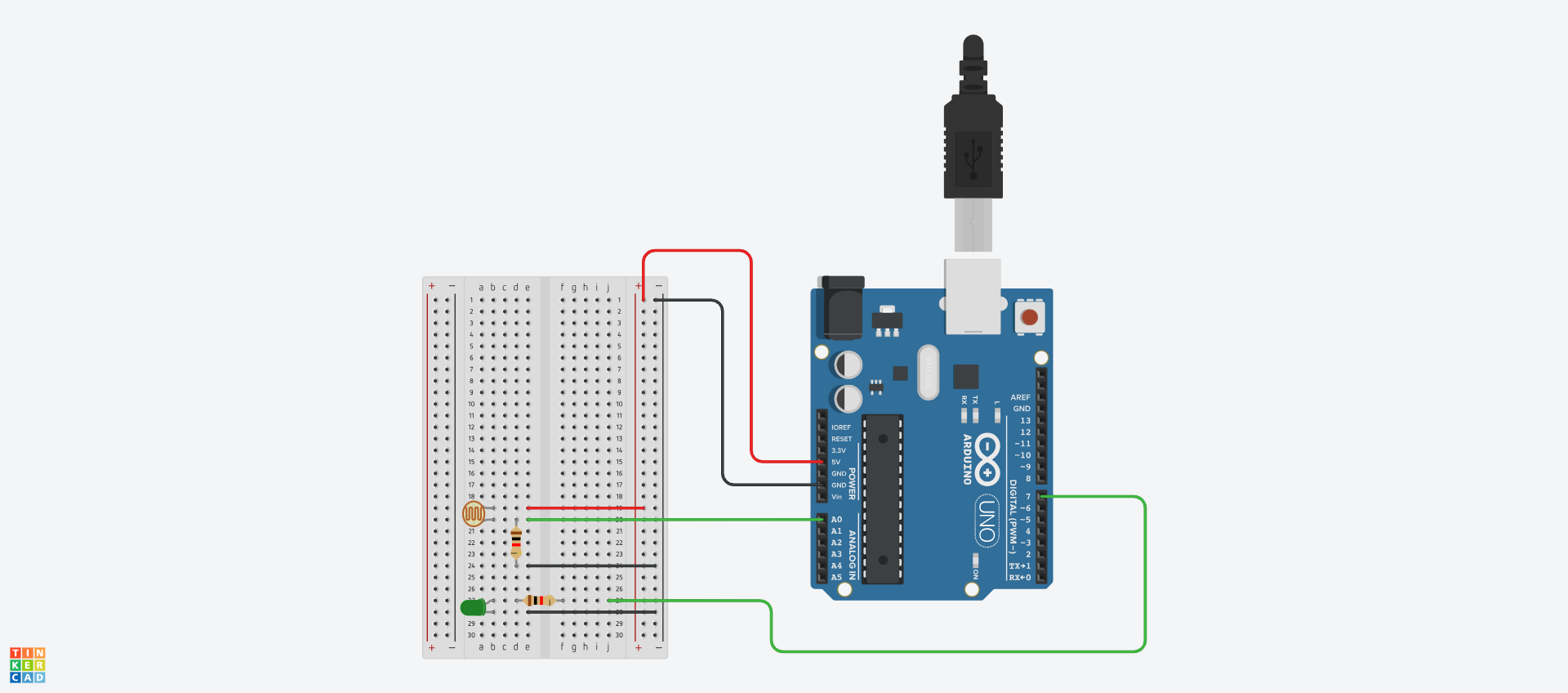
Photoresistor Connection
- Connect one leg of the photoresistor to 5V.
- Connect the other leg of the photoresistor to pin A0 and to one end of the resistor.
- Connect the other end of the resistor to GND.
LED Connection
- Connect the shorter leg to GND.
- Connect the longer leg to digital pin 7.
How to Control an LED with a Photoresistor in Arduino
Here’s the full project code:
int sensor = A0;
int sensorReading;
int greenLED = 7;

void setup() {
  Serial.begin(9600);
}

void loop() {
  sensorReading = analogRead(sensor);
  Serial.println(sensorReading);

  if (sensorReading < 300) {
    digitalWrite(greenLED, HIGH);
  } else {
    digitalWrite(greenLED, LOW);
  }
}
Let’s break it down:
Variable Initialization
int sensor = A0;
int sensorReading;
int greenLED = 7;
We started by initializing variable to match the connections on the board. The photoresistor—denoted by the sensor—has a value of A0, which corresponds with the sensor connected to pin A0 on the board.
Similarly, greenLED was initialized with a value of 7, representing the green LED connected to pin 7.
Lastly, we declared a sensorReading variable. This will be used to store the values of the photoresistor (sensor).
Serial Monitor
void setup() {
  Serial.begin(9600);
}
In the setup() function, we initialized the serial monitor with a baud rate of 9600 using the Serial.begin() function. This will be useful for printing the values of the sensor to the serial monitor.
Photoresistor Logic
sensorReading = analogRead(sensor);
Serial.println(sensorReading);
We started by reading the value of the sensor using the analogRead() function: sensorReading = analogRead(sensor). We then printed the value to the serial monitor using the Serial.println(sensorReading).
if (sensorReading < 300) {
  digitalWrite(greenLED, HIGH);
} else {
  digitalWrite(greenLED, LOW);
}
In the if statement above, the LED will turn on when the value of the photoresistor is below 300, and will go off when the value is above 300.
Go on and upload the code and see how the LED behaves based on the intensity of light on the sensor. You can use a flashlight or any light source to control the exposure of light to the sensor.
Conclusion
In this article, you learned how to connect and use a photoresistor in Arduino. You also learned how to control an LED based on the value of a photoresistor.
You can find the project code and circuit diagram here.
You can read more articles here.
Check out my YouTube channel for videos on embedded systems and web development.
Tag(s):